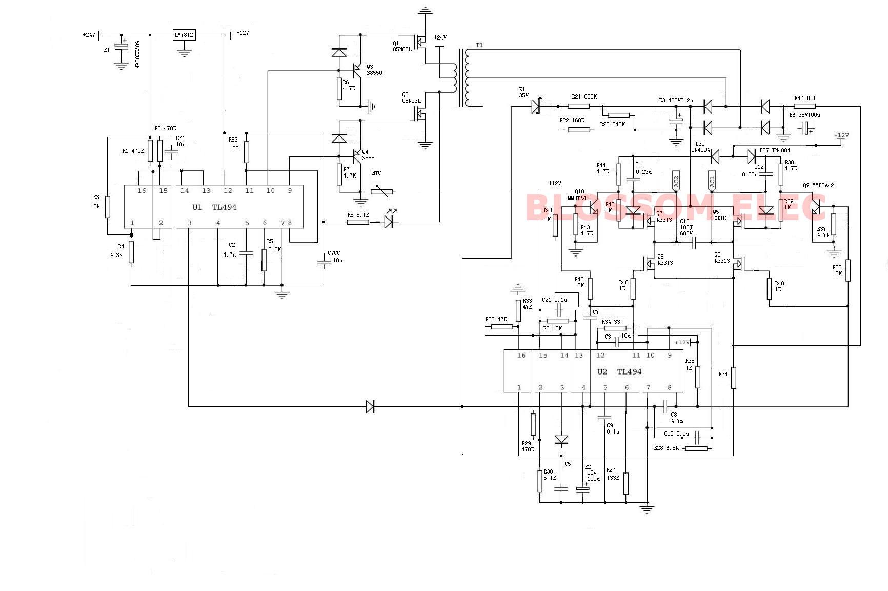
As the MOSFET is a voltage controlled device, so for turning ON the MOSFET, the Gate to Source Voltage (Vgs) must be greater than the Gate to Source Threshold Voltage (Vth).. In this method, the voltage is applied at drain and gate of MOSFET by separate power supplies.. In this configuration, When a trigger voltage is applied to the gate then MOSFET has a very low drain to source resistance i.
- mosfet driver circuit diagram
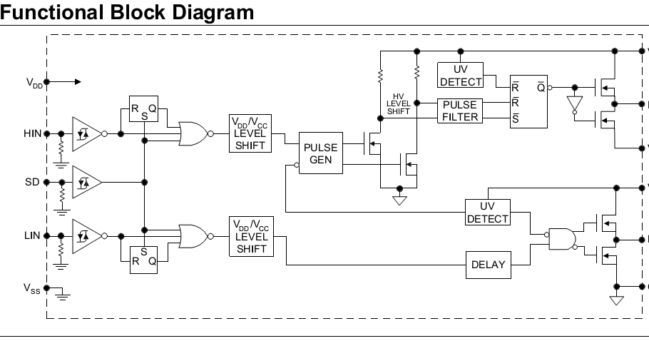
- ir2110 mosfet driver circuit diagram
- bipolar totem-pole mosfet driver circuit diagram
Ir2110 Mosfet Circuit Diagram Driver IC WhichIR2110 is a High Low side Gate Driver IC which is used with power MOSFET and IGBT.. In low side switching, there is no need of a gate driver circuit In this switching mode as the source is directly connected to the ground so.
mosfet driver circuit diagram
mosfet driver circuit diagram, irf840 mosfet driver circuit diagram, ir2110 mosfet driver circuit diagram, high side mosfet driver circuit diagram, bipolar totem-pole mosfet driver circuit diagram, mosfet gate driver circuit diagram, mosfet led driver circuit diagram, mosfet driver ic circuit diagram Lord Of All Realms Novel Wiki
Ir2110 Mosfet Driver Circuit Diagram SystemIr2110 Mosfet Driver Circuit Diagram ReplacementAbstract. Free Rapidshare Anno 1701 Deutsch

ir2110 mosfet driver circuit diagram

bipolar totem-pole mosfet driver circuit diagram

In high side configuration, the load is connected between the source of the MOSFET and the ground.. These concepts will crystal clear the working of MOSFET as a switch and will so justify the use of MOSFET in the inverter circuit as switching component.. This resistance also discharge the parasitic capacitance of the MOSFET Otherwise, the MOSFET can get damaged as this parasitic capacitor will keep on charging and exceed the limit of the gate to source breakdown voltage.. Also, do not exceed the input voltage (drain voltage and gate voltage) of MOSFET greater than its breakdown voltage as it can damage the MOSFET.. Ir2110 Mosfet Circuit Diagram Driver IC WhichThat means when MOSFETIGBT is used in High side configuration then a gate driver IC is needed.. A Gate Driver is a specially designed circuit that is used to drive the Gate of MOSFET or IGBT in High Side Switching application.. But the input voltage is only 5V, that means the high side MOSFET cannot be driven by applying the same voltage at the base and drain of MOSFET.. A low-value resistor (10E to 500E) should be used at the gate of MOSFET This will solve the problem of ringing (parasitic oscillations) and voltage spike in the MOSFET.. The load (shown as resistance RL in the circuit diagram) is placed in between the drain and the power supply.. Since MOSFET is a voltage controlled device, for providing appropriate voltage drop at the terminals of the MOSFET, some resistors need to be connected at the gate and source of the MOSFET. b0d43de27c


0